I am building an extruder based on
Droftarts' Sliced Wade's Extruder.
 |
| Basic body parts for extruder |
This design has the advantage that all the structural parts are flat and of the same thickness, and that almost all the cutouts can be made with drills, working in the easy direction.
I made the basic parts a while ago, without paying too much attention to how the extruder was supposed to be constructed and function. As a result, a few things are a touch suboptimal.
 |
| Dremel 22m holes to fit bearings |
The holes for the bearings and motor are nominally 22mm. My drill was measurably less that 22mm, which was good for the stationary bearings, as I was able to sand out their holes quickly with a dremel to give a good tight fit. The mobile bearing needs a bit of slack around it, so it took rather longer with a dremel to get enough space. For the motor, the bezel around the shaft is a bit more than 22mm diameter, so I had to chamfer the hole before the motor would sit flush against the wood.
 |
| Chamfer hole so motor sits flush |
The body is made of 5 layers. These are held together by bolts at the corners. Each layer is 9mm thick so the body is 45mm and I needed 50mm bolts to hold it together. Unfortunately I had already invested in a large box of M4 x 40mm socket cap bolts, so I looked for a way to manage with these slightly shorter screws.
 |
| Countersinking M4 nuts |
The head end of the hole is already countersunk in the design, so all I had to do was countersink the nuts as well. I used a sharp 4mm chisel to cut the countersink. First use a bolt to hold the nut in the correct position (see bottom right, sort-of), and trace its outline accurately by pressing the chisel into the angle (see bottom left), then remove 4-5mm of wood by cautiously cutting it into small chips. Don't try to lever too much out at once, as this may round the edges of the hole, or split the wood.
I had drilled these holes 5mm in diameter, as shown on the plan; this resulted in an assembly that was excessively floppy with my 4mm diameter bolts, until they were fully tightened. I would have done better to check what bolts I had available and drill holes better adapted to their size, say 4.1mm.
I had planned to hobb an M8 bolt with partly smooth shank for the drive, but was unable to find a suitable one in the local (smallish) DIY shop. Plan B was to use an off-cut of the 8mm diameter steel rod we use in organ building, but this turned out to be some sort of hard tool steel (known in the french speaking workshop as
stub, but this term resists my Google skills), and was entirely resistant to my efforts at hobbing.
I proceeded to Plan C. I cut a length of 8mm studding and arc welded a nut on the end. I then put the rod in a vertical drill and used a 3mm file (actually a chainsaw file) to cut a groove. The file needs a very firm support if it is not to be displaced by the thread, and of course you must work on the side of the rod which pushes the file towards the support.
 |  |  |
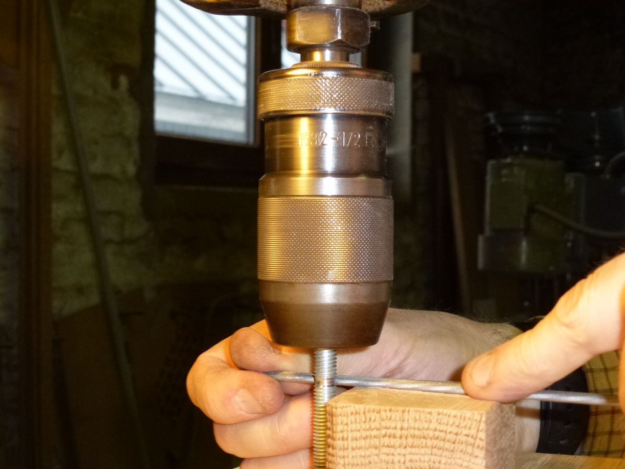
| Cutting groove with a chainsaw file | Hobbing | The feeble result |
I used a 3mm tap in a cordless drill to actually cut the hobbing in the groove. I made jig out of a block of oak, with appropriately positioned holes to support the bolt and guide the tap against it. I regarded this as only partially successful. It was hard to position to holes accurately, the solid jig concealed the operation from view and did not allow the bolt to turn freely, and it did not provide a safe way to press the tap progressively closer to the bolt. I did succeed in cutting a light pattern, and would have attempted to do better, had I not snapped the tap while taking a photo one-handed.
 |  |  |
| Countersinking the bolt head | | Nice countersink, poor weld |
 |
| Checking position of filament |
When tried assembling the parts, it was evident the slots in which the idler shaft slides were too short, and prevented the idler pushing against the filament. Also, that the bearing plus washer either side was thicker than the wooden layer they were supposed to fit into, and would prevent the layers either side from making proper contact.
A few minutes with file and dremel corrected both these problems.
 |  |  |
 |  |  |
| Putting the layers together |
 |
| The assembled extruder |
Once the extruder was assembled I checked the gears properly. After adjusted the separation so that it was possible to turn the gears quite easily, I turned them by hand to find the places where there was abnormal resistance. I could usually see defect - an abnormally thick tooth, a shallow gap or a rough edge - and corrected them systematically with a diamond file. Once the gears turned well in this initial position, I moved them a bit closer and repeated the process.
I tested the grip of the hobbed bolt on PLA filament and found it better than I expected, given the shallow grooves I had made. On the other hand I am not at all sure that the springless adjustment of pressure will be adequate. Another problem is that the large gear extends too far down, and I will need to add extra spacers before I can fit it on the carriage.


No comments:
Post a Comment