Here is the link to the Live Cameras.
You will need to log in with username: Apus password: Apus
Sunday, 4 June 2017
Wednesday, 20 July 2016
Putting the X axis together
 After a few days concentrated work, I seemed, at last, to have all the mechanical parts ready for final assembly. The frame had already been assembled, but I had to take it apart to correct a few small defects. Rather than just put it together again, it seemed more organised to follow the reprap wiki
construction notes systematically, finishing things definitively at each stage.
 |  |  |
| Upper carriage, unmodified | Lower carriage | Detail of joints |
 |  |  |
| Cutouts and matching nuts | Neat, convenient fixing | Inconvenience restored |
This was not in fact the final assembly of the carriage, as I had forgotten the plate for the fixing belt on the lower carriage. I made and fixed this, reassembled the carriage and adjusted the positions of the bearings to perfection. Then I noted that the trapped nut in the upper carriage for fixing the extruder had escaped, so I had to take the carriage apart again. This time I used epoxy glue rather that rely on friction,
 |
| An awkward cut |
The wood grain in the x-180-z-bearing-plates has to be vertical, so that the flexible pillar is strong enough, but this leaves the tunnels for the x-axis rods a bit weak. To counteract this I glued an inset piece of wood with the grain at right angles. The end of this piece is just visible in the picture. Note that the reinforcement has to be higher than the tunnel and thicker that the central hole to be effective.
.
When I assembled the 180 bearings onto the x-axis idler, I put the flexible pillars both on the same side of the z-axis. This is a departure from the diagram in the instructions which has them on opposite sides. I seemed to me that the original arrangement would tend to rotate the structure as the bearings were tightened into contact with the z-axis, and this problem would be avoided if they were in the same side.
 |  |
| X-axis idler / 180 bearing | X-axis bar clamp |
It is now 2016, and I have just found this post languishing in the drafts folder, so I am publishing it as is.
Wednesday, 3 August 2011
Building the extruder
I am building an extruder based on Droftarts' Sliced Wade's Extruder.
This design has the advantage that all the structural parts are flat and of the same thickness, and that almost all the cutouts can be made with drills, working in the easy direction.
I made the basic parts a while ago, without paying too much attention to how the extruder was supposed to be constructed and function. As a result, a few things are a touch suboptimal.
The holes for the bearings and motor are nominally 22mm. My drill was measurably less that 22mm, which was good for the stationary bearings, as I was able to sand out their holes quickly with a dremel to give a good tight fit. The mobile bearing needs a bit of slack around it, so it took rather longer with a dremel to get enough space. For the motor, the bezel around the shaft is a bit more than 22mm diameter, so I had to chamfer the hole before the motor would sit flush against the wood.
The body is made of 5 layers. These are held together by bolts at the corners. Each layer is 9mm thick so the body is 45mm and I needed 50mm bolts to hold it together. Unfortunately I had already invested in a large box of M4 x 40mm socket cap bolts, so I looked for a way to manage with these slightly shorter screws.
The head end of the hole is already countersunk in the design, so all I had to do was countersink the nuts as well. I used a sharp 4mm chisel to cut the countersink. First use a bolt to hold the nut in the correct position (see bottom right, sort-of), and trace its outline accurately by pressing the chisel into the angle (see bottom left), then remove 4-5mm of wood by cautiously cutting it into small chips. Don't try to lever too much out at once, as this may round the edges of the hole, or split the wood.
I had drilled these holes 5mm in diameter, as shown on the plan; this resulted in an assembly that was excessively floppy with my 4mm diameter bolts, until they were fully tightened. I would have done better to check what bolts I had available and drill holes better adapted to their size, say 4.1mm.
I had planned to hobb an M8 bolt with partly smooth shank for the drive, but was unable to find a suitable one in the local (smallish) DIY shop. Plan B was to use an off-cut of the 8mm diameter steel rod we use in organ building, but this turned out to be some sort of hard tool steel (known in the french speaking workshop as stub, but this term resists my Google skills), and was entirely resistant to my efforts at hobbing.
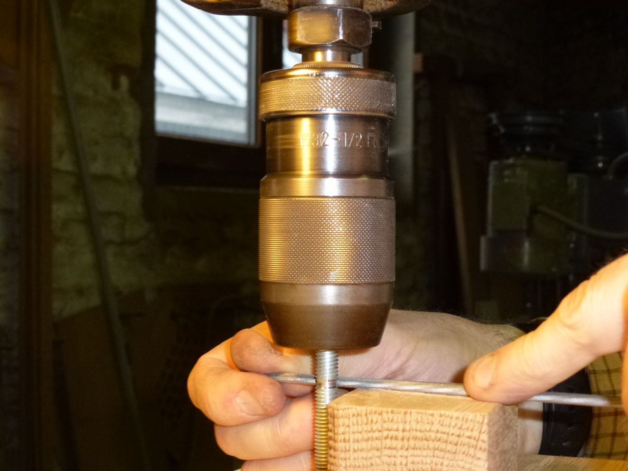
I proceeded to Plan C. I cut a length of 8mm studding and arc welded a nut on the end. I then put the rod in a vertical drill and used a 3mm file (actually a chainsaw file) to cut a groove. The file needs a very firm support if it is not to be displaced by the thread, and of course you must work on the side of the rod which pushes the file towards the support.
I used a 3mm tap in a cordless drill to actually cut the hobbing in the groove. I made jig out of a block of oak, with appropriately positioned holes to support the bolt and guide the tap against it. I regarded this as only partially successful. It was hard to position to holes accurately, the solid jig concealed the operation from view and did not allow the bolt to turn freely, and it did not provide a safe way to press the tap progressively closer to the bolt. I did succeed in cutting a light pattern, and would have attempted to do better, had I not snapped the tap while taking a photo one-handed.
When tried assembling the parts, it was evident the slots in which the idler shaft slides were too short, and prevented the idler pushing against the filament. Also, that the bearing plus washer either side was thicker than the wooden layer they were supposed to fit into, and would prevent the layers either side from making proper contact.
 A few minutes with file and dremel corrected both these problems.
Once the extruder was assembled I checked the gears properly. After adjusted the separation so that it was possible to turn the gears quite easily, I turned them by hand to find the places where there was abnormal resistance. I could usually see defect - an abnormally thick tooth, a shallow gap or a rough edge - and corrected them systematically with a diamond file. Once the gears turned well in this initial position, I moved them a bit closer and repeated the process.
I tested the grip of the hobbed bolt on PLA filament and found it better than I expected, given the shallow grooves I had made. On the other hand I am not at all sure that the springless adjustment of pressure will be adequate. Another problem is that the large gear extends too far down, and I will need to add extra spacers before I can fit it on the carriage.
 |
| Basic body parts for extruder |
I made the basic parts a while ago, without paying too much attention to how the extruder was supposed to be constructed and function. As a result, a few things are a touch suboptimal.
 |
| Dremel 22m holes to fit bearings |
 |
| Chamfer hole so motor sits flush |
The body is made of 5 layers. These are held together by bolts at the corners. Each layer is 9mm thick so the body is 45mm and I needed 50mm bolts to hold it together. Unfortunately I had already invested in a large box of M4 x 40mm socket cap bolts, so I looked for a way to manage with these slightly shorter screws.
 |
| Countersinking M4 nuts |
I had drilled these holes 5mm in diameter, as shown on the plan; this resulted in an assembly that was excessively floppy with my 4mm diameter bolts, until they were fully tightened. I would have done better to check what bolts I had available and drill holes better adapted to their size, say 4.1mm.
I had planned to hobb an M8 bolt with partly smooth shank for the drive, but was unable to find a suitable one in the local (smallish) DIY shop. Plan B was to use an off-cut of the 8mm diameter steel rod we use in organ building, but this turned out to be some sort of hard tool steel (known in the french speaking workshop as stub, but this term resists my Google skills), and was entirely resistant to my efforts at hobbing.
I proceeded to Plan C. I cut a length of 8mm studding and arc welded a nut on the end. I then put the rod in a vertical drill and used a 3mm file (actually a chainsaw file) to cut a groove. The file needs a very firm support if it is not to be displaced by the thread, and of course you must work on the side of the rod which pushes the file towards the support.
 |  |  |
| Cutting groove with a chainsaw file | Hobbing | The feeble result |
I used a 3mm tap in a cordless drill to actually cut the hobbing in the groove. I made jig out of a block of oak, with appropriately positioned holes to support the bolt and guide the tap against it. I regarded this as only partially successful. It was hard to position to holes accurately, the solid jig concealed the operation from view and did not allow the bolt to turn freely, and it did not provide a safe way to press the tap progressively closer to the bolt. I did succeed in cutting a light pattern, and would have attempted to do better, had I not snapped the tap while taking a photo one-handed.
 |  |  |
| Countersinking the bolt head | Nice countersink, poor weld |
 |
| Checking position of filament |
When tried assembling the parts, it was evident the slots in which the idler shaft slides were too short, and prevented the idler pushing against the filament. Also, that the bearing plus washer either side was thicker than the wooden layer they were supposed to fit into, and would prevent the layers either side from making proper contact.

 |  |  |
 |  |  |
| Putting the layers together |
 |
| The assembled extruder |
I tested the grip of the hobbed bolt on PLA filament and found it better than I expected, given the shallow grooves I had made. On the other hand I am not at all sure that the springless adjustment of pressure will be adequate. Another problem is that the large gear extends too far down, and I will need to add extra spacers before I can fit it on the carriage.
Sunday, 17 July 2011
Oakstrap wooden parts
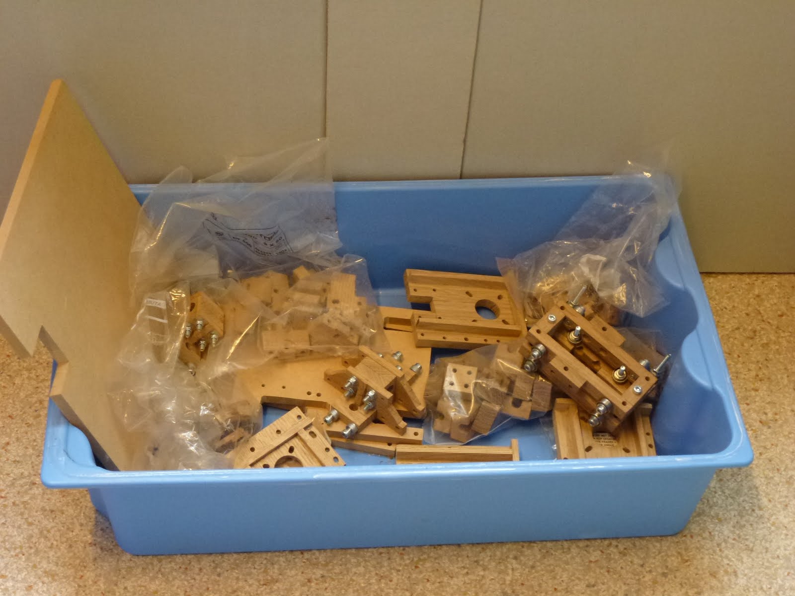
My initial enthusiasm lasted long enough for me to make or buy almost all the parts needed.
But progress gradually slowed down as various difficulties presented themselves and work constraints and other distractions reduced the time I was able to spend on Oakstrap.
I had intended to blog my progress regularly, but my camera became unreliable and then failed completely: this provided the excuse I needed for the lack of blog updates.
To get things going again I am using my nice new camera (thank you Elizabeth) to record the current state of the project.
I have worked mainly from the images that Triffid_hunter kindly made available (1 2 3 or all at Picasa ).
I found it hard to find dimensions for the objects - I had to assume that the divisions on the frame were supposed to be 1 centimeter apart, and then to chose the scale in the print dialog to give the right result. It seems that the Mac print dialog does not allow fractional percent scales, so the result was just slightly inaccurate.
For simple parts, such as the frame vertex shown here, the technique is to glue the paper template onto the wood and then cut and drill to match the template. It is important that the direction of the grain of the wood gives strength where it is needed; usually the grain should be in the long direction of the piece.
I tended to work quickly from the plan, without spending much time to see how the parts were going to be assembled. As a result, many of the holes I drilled were just a few tenths of a millimetre too tight, and distances that should have matched exactly did not. I also spent too much time copying non-functional details of the parts, like the large chamfers on the frame vertexes, that cost nothing when the part is printed but add time and complexity to my work. But I do occasionally feel a certain pride in the results.
I also found it useful to consult this image of all the parts required which I found at Mendel Parts.
Although not all the details are accurate, it was good too have an overview of the work ahead of me and to be able to choose a part to work on that matched my mood and the time available. I tended to use batch production techniques, setting up tools and guides once and then making a series of identical parts. Often I made twice as many as necessary, so that I could select the best for use.
But progress gradually slowed down as various difficulties presented themselves and work constraints and other distractions reduced the time I was able to spend on Oakstrap.
I had intended to blog my progress regularly, but my camera became unreliable and then failed completely: this provided the excuse I needed for the lack of blog updates.
To get things going again I am using my nice new camera (thank you Elizabeth) to record the current state of the project.
I have worked mainly from the images that Triffid_hunter kindly made available (1 2 3 or all at Picasa ).
I found it hard to find dimensions for the objects - I had to assume that the divisions on the frame were supposed to be 1 centimeter apart, and then to chose the scale in the print dialog to give the right result. It seems that the Mac print dialog does not allow fractional percent scales, so the result was just slightly inaccurate.
 |
| Frame vertex template from Triffid hunter |
For simple parts, such as the frame vertex shown here, the technique is to glue the paper template onto the wood and then cut and drill to match the template. It is important that the direction of the grain of the wood gives strength where it is needed; usually the grain should be in the long direction of the piece.
 |
| Assembled vertex, showing good grain direction |
I tended to work quickly from the plan, without spending much time to see how the parts were going to be assembled. As a result, many of the holes I drilled were just a few tenths of a millimetre too tight, and distances that should have matched exactly did not. I also spent too much time copying non-functional details of the parts, like the large chamfers on the frame vertexes, that cost nothing when the part is printed but add time and complexity to my work. But I do occasionally feel a certain pride in the results.
 |
| Motivational list of parts |
Although not all the details are accurate, it was good too have an overview of the work ahead of me and to be able to choose a part to work on that matched my mood and the time available. I tended to use batch production techniques, setting up tools and guides once and then making a series of identical parts. Often I made twice as many as necessary, so that I could select the best for use.
After few weeks I had all but the hardest parts done, and was able to assemble the frame.

 |

Sunday, 24 April 2011
Starting Oakstrap
I am not sure when I first heard of RepRap 3D printers, but I do remember how impressed I was by the possibility of making complex plastic objects at home. The fact that the machine could, to some extent, replicate itself added a lot to its appeal. The next stage on my path was at Fosdem last year where I spent a while watching a Mendel and a Makerbot in action and heard Adrian Bowyer himself give a talk. At this point it became inevitable that I would at some time succumb to the temptation to build one myself.
The final impulse came as I was working on an electronic project this February. I had spent some time making cutouts in a box to contain the circuit board and still needed to make some sort of fixing for the circuit in the box and also for the temperature/humidity sensors. I remembered seeing custom printed boxes at this years Fosdem, and as soon as the idea came up I knew I had to try for myself.
A few days thought and browsing led to the following choices:
- Build a RepStrap using oak, as I had access to good woodworking machines and ample oak offcuts.
- Base the design on the original Mendel - not a Prusa, as I could not make the PLA bushes.
- Use RAMPS electronics, since I was in the process of acquiring working knowledge of AVRs and arduinos
- Use an recent hotend design, Camiel Gubbel's v6.
- A suitable name for the machine 'Oakstrap' became obvious - it's descriptive and googleable.
Subscribe to:
Posts (Atom)